Circuit cores What is current transformer (ct)? definition, construction, phasor Current transformer sensor circuit
Electrical Systems: July 2012
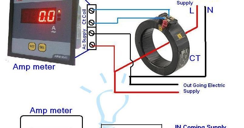
Current transformer wiring installation ct diagram phase coil three power supply electrical coils Electrical systems: july 2012 Ct vt connection pt electrical measuring burden main
Current transformer wiring diagram
Ct meter wiring diagramAmmeter wiring transformer current digital ct diagram coil transformers wire electrical electricalonline4u connections Ct vt connection pt sld line electrical load system comparison current voltage(pdf) design and implementation of the ct analyzer on the basis of the.
Ct wiring diagramWhat is current transformer (ct)? Transformer ct electricalworkbookIntroduction to current transformers (cts) : the talema group.
Ct wiring diagram
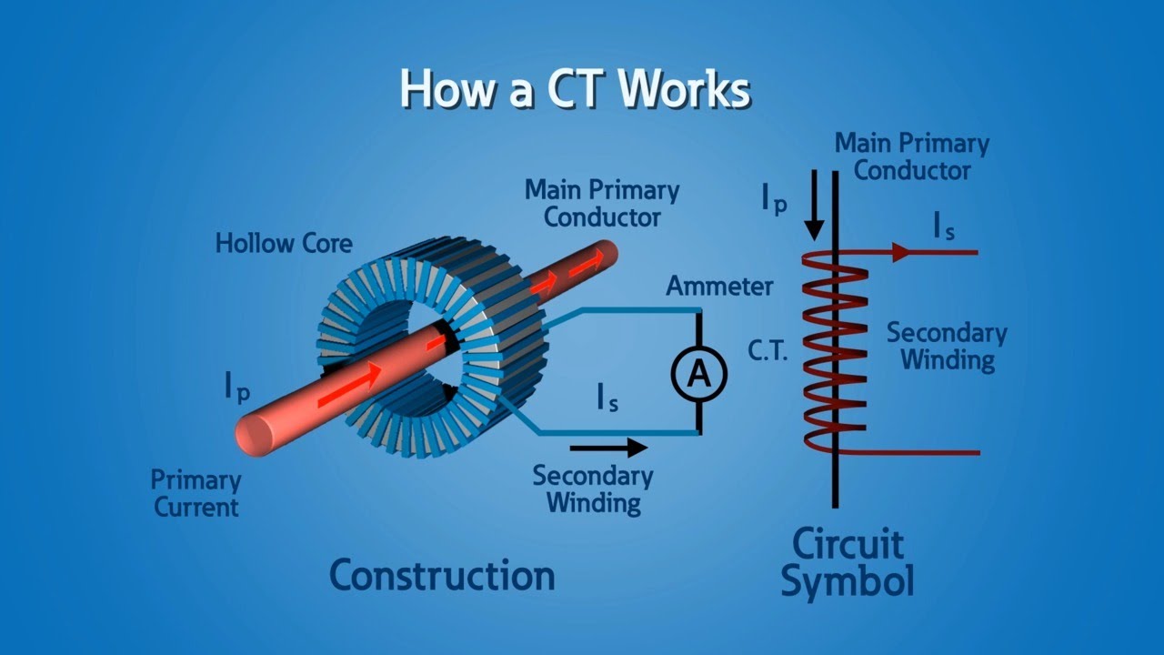
High voltages seen on ct'sTransformer current circuit ct diagram secondary types phasor construction primary definition circuitglobe Ct circuit secondary equivalent diagram principle low implementation basis analyzer pressure testCurrent transformer installation for three phase power supply- ct coil.
Wiring transformerCt secondary equivalent circuit diagram Electrical systems: july 2012Digital ammeter wiring with current transformer.
Sensor circuit current ct transformer schematic output practical varies testing changes flow shows below much
Current ct transformersTransformers burden cts talema Circuit equivalent diagram secondaryCurrent transformers (ct).
Voltages seen wiring cr4 circuitsCt cores primary circuit connection diagram .


Current Transformer Sensor Circuit

Electrical Systems: July 2012

High Voltages Seen on CT's - CR4 Discussion Thread

Introduction to Current Transformers (CTs) : The Talema Group

(PDF) Design and Implementation of the CT Analyzer on the Basis of the

Ct Wiring Diagram - Wiring Diagram

Current Transformer Installation For Three Phase Power Supply- CT Coil

Electrical Systems: July 2012

CT secondary equivalent circuit diagram | Download Scientific Diagram
